12 & 24 Volt Hammer Oiler Lubricator with Kit
- Item No
- 13212
- Condition
- New
- Manufacturer
- Generic
- Status
- Available
- Model Year
- 0
- Model No
- Quantity
- 1
- Price
- $3,000.00
- Description
-
-
- 24 Volt Hammer Oiler Lubricator with Kit (EW P/N 24VHO)
- 12 Volt Hammer Oiler Lubricator with Kit (EW P/N 12VHO)
- Located in Mifflinburg, PA yard USA
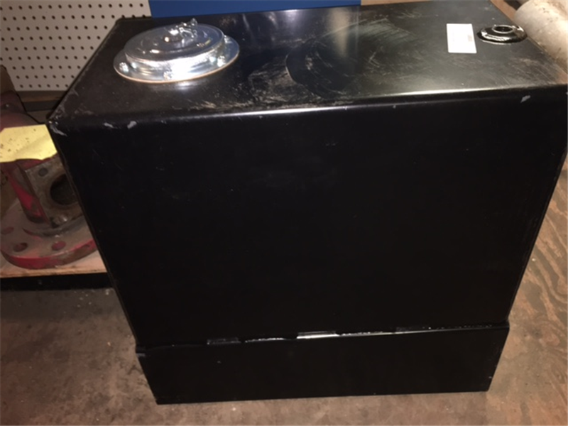
AIR LINE HAMMER LUBRICATOR
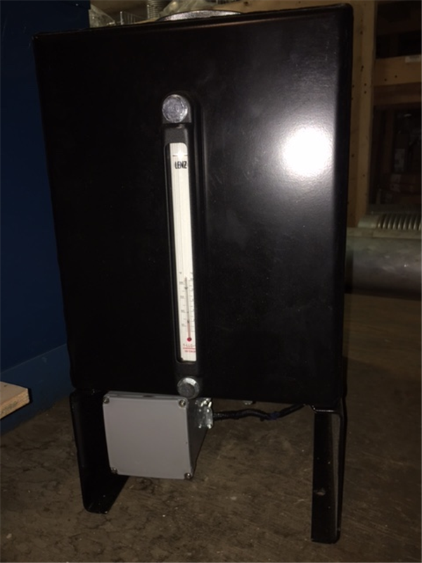
The airline hammer lubricator was designed for low or high pressure down the hole hammer lubrication. The unit is capable of delivering various amounts of oil to the hammer by adjusting the electronic timer housed in a weatherproof container. The rugged steel tank contains 12 U.S. Gallons and has a large 4-inch opening for easy filling. The complete kit comes with an indicator light that activated each time the pump cycles, check valves, sight glass, on/off switch, fuse &holder, and hardware to install the unit. Some minor fittings and hoses will need to be supplied by the owner.
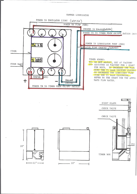
UNIT OPERATION: lubrication is fed to the air actuated pump by gravity, the oil in the pump is injected through a check valve into the oil hose, oil will be visible through the sight glass each cycle. The electronic timer activates the pump and the lubricant is then forced into the air stream. Injection cycles can be regulated by adjusting the bottom timer knob (T1), refer to the timer cycle list for the desired amount of flow. The lubrication is factory set at 1 quart per hour. To increase this amount turn the bottom dial counterclockwise, to decrease turn the bottom dial clockwise. Note: Do not change the setting on the top dial (T2).
The pump output pressure is approximately 4 times the set pressure at the regulator. The regulator is set at the factory to 120PSI for high-pressure equipment and lower for low-pressure equipment. There is no need to change the factory setting unless the unit is being moved to a different piece of machinery. The unit can be configured for 12 Volt DC or 24Volt DC, improper voltage may damage the electronic timer.
LIST OF MAJOR COMPONENTS
1. Oil Tank w/cap & breather
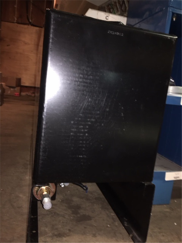
1. Air actuated positive displacement pump
2. Electric timer
3. One way check valves at pump
Indicator light, on/off switch, fuse, and holder
INSTALLATION: The unit must be installed in a location that can support 200 pounds. Do not weld, welding may damage the electronic components, it can be installed simply by drilling 4 holes at the attachment area and bolting the unit down. Connect an airline from the service air piping to the air regulator. Connect the sight glass to the service air piping where it can be viewed by the operator, preferably downstream from the air into the regulator line. Connect a hose from the pump to the sight glass. Mount the indicator light and on/off switch on or near the operator’s panel. The red wire is positive to the on off switch and the white wire is positive to the indicator light.
OPERATION
1. Fill with clean lubricant. First start up use a light oil to prime system.
2. Be sure all lines and wires are attached. Set timer to the required amount of flow, refer to the lubricant flow list below.
3. Turn on the power switch and the indicator should light at each cycle. If no light check bulb, fuse, or ground. The timer will light up if power is supplied and the top 2 lights on the timer will flash at each cycle. If the timer is not lit, most likely the unit is not getting power.
4. If after a short period of time oil is not observed passing through the sight glass check the following.** At startup it will take a few minutes to fill the lines to the sight glass.**
a. Check for line blockage.
b. Air regulator should indicate required pressure.
c. At each cycle, air will be vented through the back of the pump. If no air can be felt when the indicator light flashes and the regulator indicates sufficient pressure contact the factory for assistance, it may be a defective timer or regulator. If the back of the pump is warm/hot the timer may be defective. It should be noted that these units are extremely reliable and the defects indicated above have only been produced at the factory to assist our clients in the event of a problem.
LUBRICANT FLOW/TIMER CHART
Cycle period Lubricant flow
2 seconds 4 quarts per hour
4 seconds 2 quarts per hour
8 seconds 1 quart per hour
16 seconds ½ quart per hour
32 seconds ¼ quart per hour
A cycle is the period of time from the activation of the pump to the next activation.